

Every vector you have given an arrival so far leads to one turn: the one that puts the aircraft on the runway centerline, lets the crew capture the ILS, and sends it to the tower in a stable descent. That turn is a geometry problem as well as a radio call. If the geometry is wrong, the localizer needle never centers, however well the transmission was worded.
This chapter is about vectors to the ILS. It covers the shape of the final turn, the instrument system it is aimed at, and the clearance that authorizes it. It works one arrival at a time. Chapter 7 covers fitting several arrivals into one sequence for the same runway.
Downwind, base, final
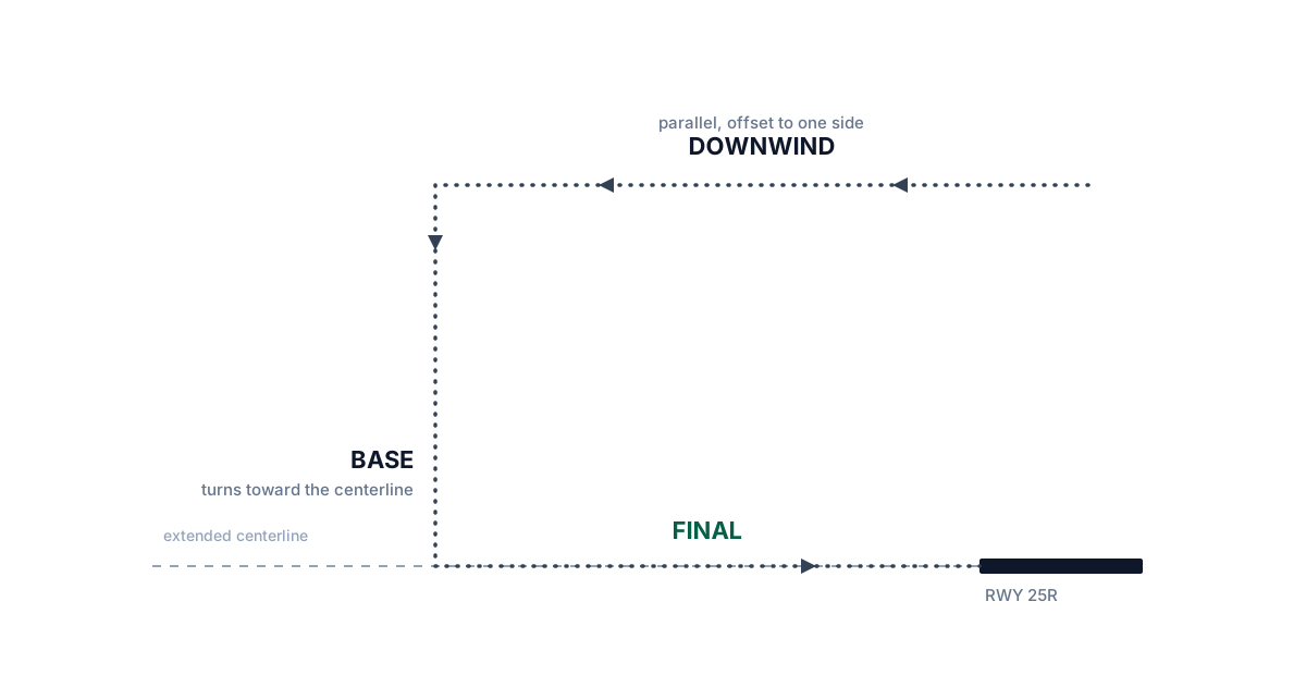
Every landing follows the same three-legged shape, whether the aircraft is hand-flown around a visual pattern or vectored through cloud by radar. Downwind runs parallel to the runway in the opposite direction to landing, offset out to one side. Base turns off the downwind and runs roughly perpendicular to the runway, in toward the extended centerline. Final is the last leg, aligned with the runway centerline and flown straight in to touchdown.
You will not draw this pattern on the scope, and with IFR arrivals you will not say downwind or base on the radio, because those are words for visual pattern traffic. The vectors you give still shape the same three legs, wider and slower than a visual pattern flies them.
- Downwind: the arrival's heading runs roughly parallel to the runway, offset to one side, while you are still sequencing and descending it.
- Base: the turn that points the arrival roughly toward the extended runway centerline and closes the distance to the airport.
- Final: the last heading, aligned with the centerline and flown straight to the threshold.
An arrival checking in from Cascade Center is, in effect, already on a long downwind. Your job is to turn it onto base and then onto final, at a place and an angle that let the second turn work.
The ILS
The instrument landing system, the ILS, is two radio beams aimed out along the runway. The localizer is the lateral beam. It is a narrow course line extending out from the runway centerline, and it tells the aircraft how far left or right of the centerline it is. The glideslope is the vertical beam. It slopes upward from the touchdown point at about three degrees and tells the aircraft how far above or below the correct descent path it is. Together they give the pilot two needles to center, one for direction and one for altitude, all the way to the runway.
The glideslope has to be intercepted from below. The beam is a sloped line rising into the sky, and an aircraft captures it cleanly by reaching it from underneath and then following it down. An aircraft that arrives at the beam from above sees the needle sweep past too fast to catch, or locks onto a false reflection of the beam that exists higher up. Every altitude you assign before the turn onto final is chosen so the arrival is at or below the glideslope by the time it gets there.
For a precision approach, at an altitude not above the glideslope/glidepath or below the minimum glideslope intercept altitude specified on the approach procedure chart.
The descent planning from chapter 5 comes back here. Get the arrival down early enough that it is at or below the glideslope at the turn, and keep it above the minimum glideslope intercept altitude printed on the approach chart.
When to turn, when to descend
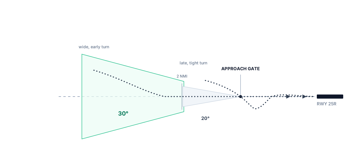
The turn onto final trades two numbers against each other: the degrees of heading change needed to point the aircraft down the runway, and the miles left to do it in. A shallow turn started well out settles onto the centerline gently and leaves room to correct if it is not perfect. The same angle started close in leaves no room. The aircraft crosses the centerline, corrects, crosses it again, and has not settled when the runway arrives. Controllers call that an unstable turn-on.
The FAA sets a limit on the intercept angle:
Assign headings that will permit final approach course interception on a track that does not exceed the interception angles specified in TBL 5-9-1.
The table caps the intercept angle at thirty degrees, and tightens it to twenty degrees when the interception point is within two miles of the approach gate. The approach gate is an imaginary point the Order places on the final approach course, one mile outside the final approach fix and never closer than five miles to the threshold. It does not appear on any chart, and every vector to final is measured against it. The usual plan turns an arrival on at least two miles outside the gate, where a thirty-degree intercept still settles with room to spare. Closer in, the aircraft has less distance to correct before the descent has to begin, and the twenty-degree limit protects that. The Order allows tighter intercepts, down to the gate itself in good weather and as close as the final approach fix when a pilot asks for it, but those leave no margin for an untidy turn. When a turn-on looks tight, fix it early: turn wider and farther out, or extend the downwind another mile or two before turning the aircraft in.
The approach clearance
Turning an arrival onto final is also a clearance, and the phraseology has four parts said together: the aircraft's position relative to a fix on the final approach course, the heading to fly, the altitude to hold until the aircraft is established on the localizer, and the approach clearance itself. Controllers remember the shape as PTAC: position, turn, altitude, clearance. If any part is missing, the pilot is short of something they need. A heading without a clearance is only a vector, a clearance without an altitude leaves the descent unresolved, and a turn without a position arrives in a cockpit that was not expecting it.
PhraseologyCLEARED (type) APPROACH.
The full clearance and its ReadbackThe pilot repeating a clearance or instruction back so the controller can verify it was received correctly.Open in the glossary, for an arrival lined up for Bayview's ILS:
American Two One Five, five miles from Solan, fly heading two two zero, maintain three thousand until established on the localizer, cleared ILS runway two five right approach.
Fly heading two two zero, maintain three thousand until established on the localizer, cleared ILS runway two five right approach, American Two One Five.
Each part does a job. The position, five miles from Solan, names a fix on the final approach course and tells the crew where they are in the picture, so the turn that follows is expected. It is the one part the pilot does not read back. The heading turns the aircraft onto the intercept geometry from the previous section. The altitude holds until the aircraft is established on the localizer, the lateral beam, and after that it keeps the aircraft safe until the glideslope comes down to meet it, so the crew never has to guess whether it is safe to start down. The clearance, cleared ILS runway two five right approach, is the legal authorization to fly the published procedure all the way to landing. The readback confirms that all of it arrived intact.
Established, and handing off to Tower
Established means more than touching the needles once. The aircraft is tracking the localizer and glideslope steadily, centered or close to it, on the right heading, and no longer correcting from the turn-on. A pilot who reports established is telling you the turn worked. If the needle swings through center and back out, the aircraft is not established yet, even if the pilot has already reported it.
Once an arrival is established, your work on that frequency is nearly done. Chapter 1 quoted the rule about transferring control only after any conflict with other traffic has been resolved, and this is where it applies. Resolve anything that still involves this aircraft, then send it to the tower promptly, after it is established and before it crosses the final approach fix. The Order wants the frequency change made by that fix, because inside it the crew's attention belongs to the approach. Handing off before the aircraft is established puts a still-turning aircraft on another frequency with nobody watching it settle, and holding the handoff too long leaves the tower clearing a landing with seconds to spare.
American Two One Five, contact Bayview Tower one one eight point three.
Contact Bayview Tower one one eight point three, American Two One Five.
That is your last transmission to the flight. Bayview Tower takes it from there to the runway.
In the Sim
ATC Simulator enforces the geometry in this chapter as well as the radio call. Turn an arrival onto final at too sharp an angle and the intercept fails the way a real one does: the localizer needle sweeps past and the aircraft flies through the centerline without capturing it. A late or too-tight turn-on is not rescued by the game. Within two miles of the approach gate the twenty-degree limit applies, and a turn that exceeds it voids the approach clearance, the same way an approach flown from that geometry would end in a go-around. That failure is scored.
To judge a turn before you make it, the sim draws distance ticks along the extended runway centerline, numbered every fifth mile out from the threshold. Count the ticks between your intended turn-on point and the approach gate and you have the same distance the interception-angle limits are built on. Once an arrival is lined up and stable, the last step in the sim is the same as the real one: contact Bayview Tower one one eight point three, and the flight is out of your hands.